
When your welder won’t strike an arc consistently or your electrode keeps sticking during use, the problem likely stems from a poor electrode holder connection. A loose or corroded cable connection at this critical junction creates electrical resistance that sabotages your welding performance. This guide delivers the exact steps professional welders use to create secure, high-conductivity connections that deliver reliable arc starts and consistent weld quality. You’ll learn why copper interface materials matter, how to prepare your cable correctly, and the precise torque specifications that prevent common connection failures.
Copper Interface Materials That Prevent Connection Failures
Your electrode holder connection relies on copper interface materials to bridge the gap between cable and clamp. These aren’t optional accessories—they’re critical components that prevent cable damage while maximizing electrical flow. Without proper copper interface materials, the steel clamp mechanism crushes your cable strands during tightening, creating hot spots and inconsistent current flow.
Essential Copper Components for Optimal Conductivity
Primary copper types available:
– Pre-formed copper tube: Slides directly over cable ends, sized for standard welding cables
– Flat copper sheet: 1-inch square pieces for wrapping around cable strands
– Radiused copper strip: Pre-curved strips that match cable circumference perfectly
Copper’s superior conductivity reduces resistance at the connection point, which means less heat buildup and more power reaching your electrode. The copper interface also prevents the steel clamp mechanism from crushing your cable strands during tightening. When properly installed, these materials create a seamless electrical pathway that eliminates voltage drop and ensures consistent arc performance.
Cable Preparation Steps for Perfect Connection
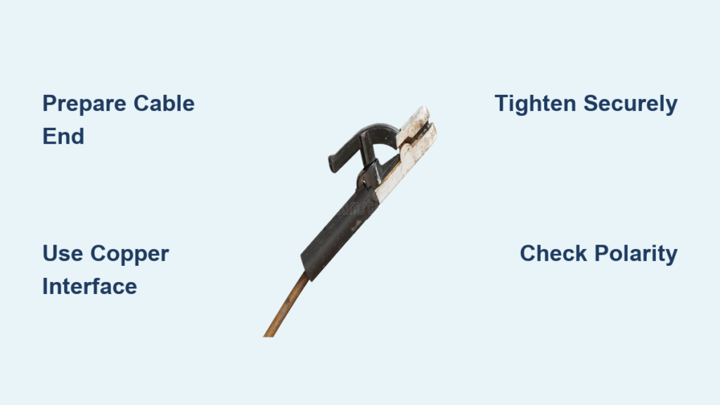
Strip and Prepare Cable End Properly
Start by removing 2-3 inches of outer insulation from your welding cable. The exact length depends on your holder design, but you need enough exposed wire to fully engage the clamp mechanism while maintaining cable flexibility. Cut insulation cleanly with a sharp knife—ragged cuts lead to future problems. Twist copper strands tightly to prevent fraying and remove any oxidation or discoloration from exposed copper. Ensure strands form a solid bundle without loose wires that could cause arcing.
Apply Copper Interface Material Correctly
Choose your copper interface method based on available materials:
For copper sheet wrapping:
– Center the 1-inch square over cable end
– Wrap completely around, overlapping slightly
– Ensure full coverage with no exposed strands
For copper tube insertion:
– Slide tube over prepared cable end
– Push until fully seated against insulation
– Tube should grip cable firmly without crushing
This copper layer creates a protective barrier that distributes clamping pressure evenly across the cable strands. Without it, the steel clamp cuts into the copper wires, creating weak points that fail prematurely under welding currents.
Step-by-Step Electrode Holder Connection Process
Primary Connection Sequence for Maximum Security
With your cable prepared and copper interface in place, follow these precise steps:
- Insert cable: Push prepared cable end into holder receptacle until fully seated
- Tighten clamp: Turn Allen screw clockwise until snug, then add 1/4 turn
- Test security: Gently pull cable—should not move or rotate in holder
- Check alignment: Ensure cable enters holder straight without stress
Apply firm pressure but avoid over-tightening. The copper interface should compress evenly without cutting into cable strands. If using a torque wrench, aim for 15-20 ft-lbs for standard electrode holders. This specific torque range creates optimal contact pressure without damaging the connection.
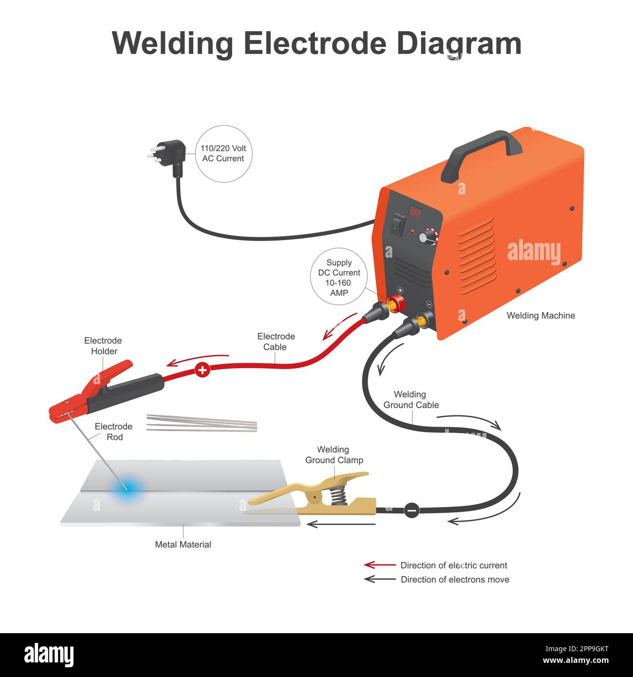
Polarity Configuration Guide for Optimal Performance
Standard DC Hookup for Most Welding Applications
Connect your electrode holder to the positive (+) terminal on your power source. The work return cable attaches to negative (-). This straight polarity works for most electrodes and provides deep penetration. Before welding, verify polarity with a test weld on scrap material to confirm proper setup.
Connection checklist:
– Electrode holder → positive terminal
– Work clamp → negative terminal
– Tighten all terminal connections with proper wrenches
– Verify polarity with test weld on scrap material
When to Use Reversed Polarity Setup
When welding certain electrode types (like 7018), reverse polarity delivers better results. Simply swap your electrode holder and work return cable positions on the power source terminals. This configuration provides smoother arc characteristics and improved bead appearance with specific electrode formulations.
Troubleshooting Common Connection Problems

Fixing Intermittent Arc Starts Immediately
Loose cable symptoms:
– Intermittent arc starts
– Electrode overheating at holder
– Visible sparking from connection point
Fix immediate issues:
– Power down welder completely
– Remove cable from holder
– Clean contact surfaces with wire brush
– Retighten connection following proper sequence
Poor connections manifest as inconsistent bead appearance, excessive spatter levels, electrode sticking problems, and holder heating during use. These issues often trace back to improper copper interface application or insufficient clamping force.
Emergency Field Repair Solutions for Damaged Connections
Creating Temporary Copper Pipe Connections
When proper materials aren’t available:
Copper pipe substitute:
– Use 8mm microbore central heating pipe
– Cut 1-1.5 inch length with tubing cutter
– Anneal before use for better compression
Annealing procedure:
– Heat pipe segment with propane torch until cherry red
– Allow to air cool or quench in water
– Softened copper crushes uniformly instead of splitting
This emergency technique creates a robust cable end that maintains conductivity until proper replacement materials arrive. The annealing process softens the copper to prevent cracking under clamp pressure.
Weekly Maintenance Checks for Long-Lasting Performance
Critical Inspection Points for Connection Integrity
Inspect your electrode holder connection every 25-30 hours of welding time:
Critical inspection points:
– Allen screw tightness—should not loosen under vibration
– Cable condition at entry point—look for insulation damage
– Copper interface integrity—check for crushing or deformation
– Overall cable flexibility—stiff sections indicate internal damage
Regular inspections catch developing problems before they cause welding failures. Pay special attention to the cable entry point where repeated movement creates stress fractures in the copper strands.
Replacement Indicators: When to Install a New Connection
Recognizing Connection Failure Signs
Replace the entire connection assembly when you notice:
– Failure to release electrode stubs easily
– Visible cable strand breakage
– Persistent overheating during normal use
– Crushed or deformed copper interface material
Note: Copper interface materials typically deform permanently during use and cannot be reused after removal. Always use fresh copper material when making new connections to ensure optimal conductivity.
Pro Tips for Long-lasting Electrode Holder Connections
Installation Best Practices That Prevent Future Problems
- Clean all contact surfaces with emery cloth before assembly
- Use dielectric grease on outdoor connections to prevent corrosion
- Route cables to avoid sharp bends at holder entry point
- Secure cables with strain relief to prevent connection stress
Before starting any welding project, perform these final checks:
1. Mechanical test: Pull firmly on cable—should not budge
2. Electrical test: Strike arc on scrap—should start immediately
3. Thermal test: Holder should stay cool during short test welds
4. Visual inspection: No sparking or arcing at connection point
A properly connected electrode holder delivers consistent performance, extends cable life, and eliminates most arc starting problems. Take time to do it right the first time, and you’ll spend more time welding and less time troubleshooting. For high-current applications requiring maximum conductivity, consider soldering the connection by applying flux to the copper pipe interior before cable insertion, heating the assembly until flux bubbles, and flowing solder into the pipe end until full. This creates a permanent, void-free connection ideal for production welding or high-duty cycles.


