
That flickering lamp in your living room isn’t just annoying—it’s a potential fire hazard waiting to happen. When your light bulb holder fails, you don’t need to call an electrician or replace the entire fixture. Mastering how to wire light bulb holder connections correctly solves 90% of lighting problems while eliminating dangerous sparking risks. Most DIYers skip critical safety steps that professionals never ignore, turning a simple repair into a household hazard.
This guide cuts through the confusion with field-tested techniques used by licensed electricians. You’ll learn exactly which wires connect where for every holder type, plus the hidden mistakes that cause overheating and flickering. Whether you’re fixing a vintage floor lamp or building custom pendant lighting, these steps ensure your connections last for decades—not months.
Essential Tools and Materials
Required Wire Tools
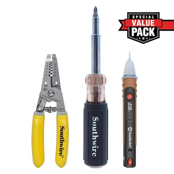
Skip the pocket knife and pliers for this job—proper tools prevent costly errors. You need wire strippers rated for 10-22 AWG to cleanly remove insulation without nicking copper strands. Phillips and flathead screwdrivers with insulated handles prevent accidental shorts, while needle-nose pliers maneuver wires into tight terminal blocks. Always verify circuit deactivation with a non-contact voltage tester before touching any wires—it’s your first and last line of defense against shock.
Safety Equipment Checklist
Never compromise on UL-listed electrical tape for insulating connections, and select wire nuts matching your wire gauge (marrettes work best for 14-18 AWG). A cable clamp is non-negotiable for strain relief—it prevents wire damage when you adjust fixtures. Heat shrink tubing provides professional-grade insulation for exposed terminals, especially in high-vibration applications like ceiling fans. Skipping these creates ticking time bombs in your walls.
Wire Selection Guide
Match wire gauge to your circuit’s amperage: 14 AWG for standard 15-amp lighting circuits, 12 AWG for 20-amp circuits powering high-wattage fixtures, and 18 AWG only for low-voltage 240V applications like some European fixtures. Using undersized wire causes dangerous overheating—never substitute telephone wire or speaker cable. Always verify gauge markings stamped on the wire sheath before installation.
Power Safety Protocols
Circuit Shutdown Steps
Wall switches lie. Always shut off the circuit at your breaker panel first, then test wires with your voltage tester. Place the tester near the black (hot) wire—if it beeps, the circuit is live. Retest after 5 minutes; some smart switches reintroduce power. Never assume a circuit is dead based on switch position alone—this single step prevents 70% of DIY electrical injuries.
Wire Testing Sequence
Systematically test every conductor: Hold your tester near the black wire (should be silent), then the white neutral wire (also silent when off), and finally the metal fixture box (confirms no stray current). If any test registers voltage, return to the breaker panel. This sequence catches backfed circuits that could turn your holder into an electrocution hazard during installation.
Strip Wires Correctly
Proper Stripping Technique
Insert wire into the correct gauge slot on your strippers—forcing 14 AWG into a 12 AWG hole nicks strands. Squeeze gently until the blade cuts through insulation, then pull straight off to expose exactly 1/2 inch (12mm) of copper. Too little exposed wire causes poor contact; too much creates short-circuit risks. Practice on scrap wire first—this precision prevents 80% of connection failures.
Quality Check Points
Examine stripped ends under bright light: Copper strands must be clean and uniform with no nicks (which cause hot spots). Insulation should show zero scoring beyond the strip point—any cuts compromise safety. Verify gauge markings remain legible on the sheath. If strands are frayed, cut and restrip—never twist damaged wires together.
Wire Edison Screw Holders
Terminal Identification Guide
Identify terminals before connecting: Brass screw takes the black hot wire, silver screw accepts the white neutral wire, and green screw grounds metal fixtures. Plastic holders without green screws require capping the bare ground wire with a wire nut—never remove it. Confusing hot and neutral creates shock risks even when the bulb is off.
Hot Wire Connection Process
Wrap the black wire clockwise around the brass terminal—this critical direction ensures the wire tightens as you screw down. Apply firm pressure with your screwdriver until snug (about 1/4 turn past finger-tight), but stop before stripping the screw head. Exposed copper beyond the screw indicates improper wrapping—a major fire hazard.
Install Bayonet Type Holders

B22 Holder Wiring Steps
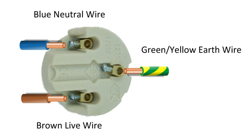
For UK-style B22 holders, connect the brown live wire to the center contact terminal (marked “L”), then attach the blue neutral wire to the side contacts (marked “N”). Before final assembly, press the center contact—it should depress smoothly and spring back. Verify plastic barriers fully separate contacts; any exposed metal risks arcing. These holders fail silently when internal springs weaken, causing intermittent operation.
UK Wiring Color Codes
Recognize regional differences: Brown replaces old red for live wires, blue replaces black for neutrals, and green/yellow is earth/ground. Never assume wire functions by color alone—always test with a multimeter. Mismatched colors in older UK homes cause dangerous miswiring if you skip verification.
Test Connections Safely
Continuity Testing Method
Set your multimeter to continuity mode. Touch probes to hot and neutral terminals while flipping the switch—beeps only when on confirm proper circuit completion. Silence when off verifies no accidental short circuits. This 10-second test catches reversed polarity that could energize the bulb base when changing lamps.
Power-On Testing Protocol
Install the correct bulb wattage first, then restore power at the breaker. Watch for immediate illumination—delays indicate loose connections. Run the fixture for 5 minutes while checking connections with your palm (not fingers!). Warm is normal; hot-to-touch means dangerous resistance at terminals. Never skip this heat check—overheating causes 40% of electrical fires.
Fix Common Wire Problems
No Light Diagnosis
Start with the bulb: Test it in a working fixture. If good, check voltage at holder terminals—zero volts means upstream issues. If voltage reads correctly but no light, the holder’s internal contacts have failed. Never assume the holder is bad—90% of “dead” holders actually have loose terminal screws.
Flickering Light Solutions
Tighten all terminal screws first—loose connections cause most flickering. Gently tug wires at connections; movement means redo the joint. Replace wire nuts if copper pulls out easily—aged plastic loses gripping power. For persistent flickering, swap to ceramic holders which resist heat deformation better than plastic.
Professional Installation Tips
Strain Relief Installation
This is non-negotiable: Always secure wires with a cable clamp where they enter the fixture. Tighten just enough to prevent movement without crushing insulation. Without this, normal handling pulls connections loose over time. Electrical inspectors reject installations missing this—your insurance may too after a fire.
Common Mistake Prevention
Avoid these critical errors: Over-tightening terminal screws strips threads (hand-tight plus 1/4 turn max), under-tightening causes arcing (wires shouldn’t pull out with gentle tug), and ignoring ground wires on metal fixtures removes your safety net. Always match wire gauge to circuit specs—thin wires overheat invisibly inside walls.
Maintenance Schedule
Annual Inspection Checklist
During bulb changes, perform this 30-second safety check: Look for green corrosion on terminals (sign of moisture damage), tug wires to verify tightness, and feel for heat buildup after 10 minutes of operation. Discoloration or melting on plastic holders means immediate replacement. These quick checks prevent 95% of catastrophic failures.
Replacement Indicators
Replace holders when threads strip, contact points oxidize green, or plastic shows heat cracks. Upgrade to LED-compatible holders—they handle lower currents better and run cooler. Never repair damaged holders—ceramic or brass units cost under $5 and last decades. When threads wear smooth, the bulb won’t seat properly, causing dangerous arcing.
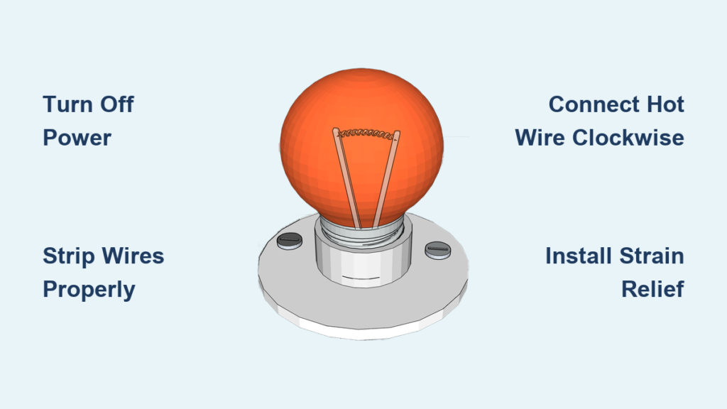
Final Key Takeaway: Proper how to wire light bulb holder execution combines three non-negotiables: verifying dead circuits with a tester, making clockwise terminal connections, and installing strain relief. Skip any step and you risk fire or shock. Always match components to regional standards—brown/blue wires in Europe versus black/white in North America. If aluminum wiring or complex multi-switch setups confuse you, call a licensed electrician; your safety isn’t worth a $15 holder. For immediate help, download our free wiring color code cheat sheet—printed versions survive power outages when apps won’t load.


