
Your overhead power line suddenly slapping against the siding during a storm isn’t just alarming—it’s a critical warning sign. When your service entrance wire holder fails, you risk dangerous electrical exposure, weather damage to wiring, and immediate utility service disconnection. Installing this crucial component correctly keeps your home’s electrical system safe while meeting strict NEC requirements that prevent fire hazards and electrocution risks. In this guide, you’ll learn exactly how to install a service entrance wire holder safely, avoid common inspection failures, and ensure your property passes utility company verification on the first attempt.
Why NEC Clearance Standards Dictate Your Wire Holder Position
Mounting your service entrance wire holder too close to windows or doors creates serious safety hazards that inspectors immediately flag. The National Electrical Code mandates 36 inches minimum clearance from all operable building openings to prevent accidental contact during storms or maintenance. Similarly, maintaining 10 feet vertical clearance above driveways and walkways prevents vehicles from snagging overhead lines—a frequent cause of service interruptions.
Permit Requirements You Can’t Skip
- Secure an electrical permit before removing old hardware
- Schedule mandatory post-installation inspection
- Obtain utility company approval in regulated areas
- Document all changes for future service calls
NEC-Compliant Material Specifications
- Mast-type holders are required for overhead residential services
- Conduit must be minimum 2-inch diameter rigid material
- Approved materials include Schedule 40 PVC or galvanized steel
- All components must carry UL certification for outdoor use
Exact Tools Needed for Service Entrance Wire Holder Installation

Attempting this job without the proper equipment compromises safety and often causes rework. Gather these specialized items before your ladder leaves the truck:
Critical installation tools:
– Impact driver with T30 Torx bits
– Torpedo level for precise bracket alignment
– Glow rods for threading wires through conduit
– Insulated wire strippers rated for 4/0 AWG
– Torque wrench for NEC-compliant fastening
Required materials checklist:
– Complete service entrance wire holder kit
– 2-inch weatherhead with drip loop
– Rigid conduit (length determined by mounting height)
– 3-inch galvanized lag screws (never use drywall screws)
– Silicone sealant rated for outdoor electrical use
– Wire pulling compound to reduce friction
– #6 copper grounding wire with UL-listed clamp
Critical Safety Steps Before Touching Power Lines
Working near utility service drops involves lethal voltage levels—never assume lines are de-energized. One misstep can cause arc flashes exceeding 35,000°F. Before climbing, complete these non-negotiable safety protocols:
Mandatory Pre-Work Verification
- Call 811 three business days prior for underground utility marking
- Confirm power disconnection at the meter with a voltage tester
- Wear Class 00 rubber gloves (rated for 500V) and non-conductive footwear
- Position a ground spotter with emergency shut-off instructions
Weather Condition Red Flags
- Immediately stop work if winds exceed 15 mph
- Never use aluminum ladders within 10 feet of power lines
- Postpone installation during rain, fog, or high humidity
- Check NOAA forecasts for thunderstorm risks 24 hours prior
How to Measure and Plan Your Wire Holder Mounting Position
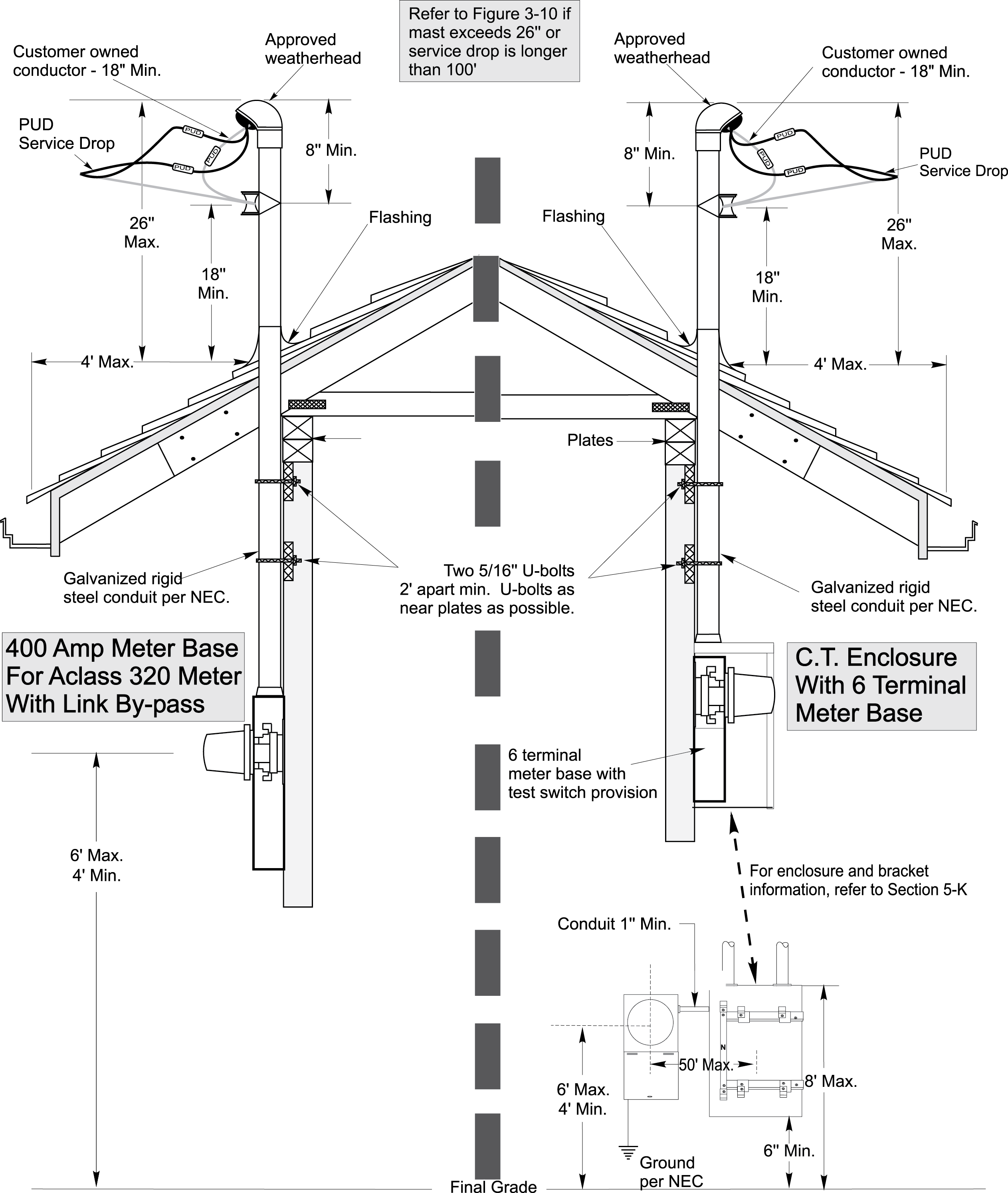
Your mounting location determines long-term safety and code compliance. Measure twice before drilling—errors here often require complete system rework. Start by measuring ground to attachment point while accounting for the required 18-inch drip loop below the weatherhead. Ensure 3-foot clearance from roof edges to prevent ice dam damage during winter.
Structural Mounting Verification
- Locate wall studs or roof rafters using a stud finder
- Never mount to vinyl siding, fascia boards, or soffits
- For masonry walls, use 1/2-inch expansion anchors rated for 100+ lbs
- Verify structural integrity by probing with a nail before drilling
Step-by-Step Removal of Damaged Wire Holders
Corroded mounting points or cracked weatherheads require immediate replacement. Begin by photographing your existing wiring configuration for reference—this prevents connection errors during reinstallation. Carefully label each conductor with colored tape before disconnecting.
Safe Disconnection Sequence
- Support wires with a temporary hook before loosening connections
- Unscrew weatherhead counter-clockwise while supporting its weight
- Remove mounting screws one at a time while holding the bracket
- Lower old components slowly using a rope—never drop hardware
Responsible Component Disposal
- Cut PVC conduit into 2-foot sections for recycling
- Separate metal parts for scrap yard recycling
- Check municipal regulations for electrical waste disposal
- Never leave debris on utility company property
Securely Mounting Your New Service Entrance Holder Bracket
The mounting bracket bears the full tension of your service drop—improper installation causes catastrophic failures during high winds. Position the bracket using a torpedo level, then pre-drill pilot holes with a 1/8-inch bit to prevent wood splitting. Apply silicone sealant around mounting holes before inserting screws to block moisture intrusion.
Load Testing Protocol
- Apply 50 pounds of downward force using a calibrated scale
- Verify zero movement at all mounting points
- Recheck level after load testing and retighten screws
- Fail immediately if any flexing occurs—reposition bracket
Correct Way to Thread Service Wires Through the Holder
Forcing wires through conduit causes insulation damage that leads to short circuits. Start by stripping 6 inches of outer jacket from the service cable ends. Carefully separate conductors while avoiding nicks to individual insulation. Apply wire pulling compound to reduce friction—this prevents jacket abrasion during installation.
Wire Feeding Technique
- Attach glow rods to wires using pulling grips
- Feed rods upward from bottom of conduit to avoid kinks
- Pull steadily while maintaining consistent tension
- Leave 18 inches of excess wire at weatherhead for drip loop
Weatherhead Sealing to Prevent Water Damage
A poorly sealed weatherhead allows rain to track down wires into your electrical panel—causing corrosion and potential fires. Slide the weatherhead over wires before forming the drip loop, ensuring the drip loop points downward away from the building. Hand-tighten compression fittings to avoid cracking the housing, then seal all seams with outdoor-rated silicone caulk.
Critical Weatherhead Positioning
- Maintain minimum 4-inch loop radius to prevent wire fatigue
- Never allow sharp bends where wires enter the weatherhead
- Verify no metal burrs contact wiring insulation
- Point drip loop away from building foundation
Essential Grounding Steps for Service Entrance Holders
Improper grounding turns your wire holder into a lightning strike hazard. Connect #6 copper grounding wire directly to your grounding electrode system using an UL-listed acorn clamp. Route this wire inside the conduit from weatherhead to grounding point—never leave it exposed. After connection, test resistance with an ohmmeter; readings must be under 25 ohms.
Post-Installation Ground Verification
- Measure resistance 24 hours after installation
- Re-torque all connections if resistance changes
- Inspect for corrosion at clamp points monthly
- Never paint over grounding connections
Pre-Inspection Checklist to Pass on First Try
Utility inspectors reject 40% of installations for fixable mounting errors. Before scheduling inspection, verify these critical points: all connections are hand-tightened then torque-wrenched to manufacturer specs, 36-inch clearances are maintained from windows, weatherhead seals show no gaps, and grounding wire follows a continuous downward path.
Documentation Must-Haves
- Clear photos of drip loop and mounting points
- Permit card visible at worksite
- Torque wrench calibration certificate
- Utility company approval documentation
Top 5 Installation Mistakes That Fail Inspections
Even experienced electricians fail inspections due to these preventable errors. Using drywall screws instead of galvanized lags causes bracket pull-out during high winds—inspectors check screw types with a magnet. Mounting to vinyl siding creates immediate failure since it can’t bear load. Ignoring the 3-foot roof edge clearance violates NEC 230.28 and risks ice damage.
Costly Wire Handling Errors
- Over-tightening wire clamps crushing conductor insulation
- Creating sharp bends in drip loops causing wire fatigue
- Leaving insufficient wire length for future utility connections
- Skipping torque specifications on compression fittings
Annual Maintenance for Long-Lasting Service Entrance Holders
Seasonal inspections prevent emergency utility calls and costly repairs. Every spring, check mounting screws for tightness using a torque wrench—wind vibration loosens connections over time. Inspect the weatherhead for hairline cracks that allow moisture intrusion. After major storms, verify wire tension hasn’t increased dangerously.
Post-Storm Damage Protocol
- Immediately report any sagging service drops to your utility
- Check for wire chafing at conduit entry points
- Document damage with timestamped photos
- Never attempt repairs on storm-damaged holders yourself
Final Verification: Before calling your utility for reconnection, complete this critical trio: measure all clearances with a tape measure, confirm torque values match manufacturer specs, and verify no tools remain on the mounting structure. A properly installed service entrance wire holder should last 25+ years when installed to NEC 230.26 standards. Remember that skipping permits or safety steps risks $5,000+ utility fines and creates life-threatening hazards—never cut corners on this mission-critical component. Schedule your inspection within 48 hours of completion while the work is fresh in your mind for any required adjustments.


